Concrete Rebar Calculator
Estimate rebar length, sticks and weight for a two-way slab grid, with cover and laps.
Slab Grid
Common slabs
Estimates only. Not professional advice.
Rebar to order
563ft
#4 (1/2") both ways at 12 in on center over a 20 by 12 ft slab, including the 10% allowance.
- Grid length before allowance
- 512 ft
- Bars each way
- 13 by 21
- Slab area
- 240 sq ft
- Steel cost range
- $282 to $507
- Steel per sq ft of slab
- $1.64
Last updated August 13, 2026. Cover and splice figures checked against ACI 318-19 and the 2021 IRC by our expert review team.
Cover and lap
Your rebar grid with cover taken off and lap splices added back
A bar count off the slab dimensions is not the steel you place. Cover stops every bar short at both ends, and any bar that outruns a stock stick has to be lapped, which puts steel back. Those two move in opposite directions, so the only way to know whether your allowance is enough is to run both.
Plan and section are each to scale on both of their own axes, but not to the same scale as each other: a 0.5 in bar is invisible at the scale of the plan. The shaded band in the section is the position IRC R506.2.4 allows, not a cover dimension.
Counted against detailed
- Grid as counted
- 512 ft
- Cover off both ends
- - 17 ft
- Lap steel added back
- + 0 ft
- Steel as detailed
- 495 ft
- Your order length
- 563.2 ft
Nothing splices at this size: the longest clear run is 19.5 ft against a 20 ft stick. Laps start once a slab dimension passes 20.5 ft.
Grid as drawn
- Bars the long way
- 13 at 19.5 ft
- Bars the short way
- 21 at 11.5 ft
- Spacing achieved
- 11.5 in
- Lap per splice
- 20 in
An edge cover of 3 in on a 4 in slab is more than half the slab thickness. ACI 318-19 asks for 3 in against earth, and a slab that thin cannot deliver it in every direction at once, which is one of the reasons a slab on ground over a base and a vapor retarder is detailed by position instead.
Bar schedule
Rebar sizes #3 to #6 by diameter, weight, lap length and cost
The bar number is the diameter in eighths of an inch, which is why a lap quoted in bar diameters doubles between #3 (3/8") and #6 (3/4"). Weight follows the diameter under ASTM A615 and does not move with the grade.
The lap column is 40 bar diameters, which is the figure carried in the advanced options above and the default most residential drawings use. It is not an ACI number: ACI 318 works a tension lap out from development length, so the real figure moves with concrete strength, bar grade, spacing and cover. Costs are per ft at a steel supplier; hardware-store sticks usually run higher, and mill pricing moves several times a year.
Tie wire
Setting out and tying a rebar grid before the truck arrives
The count is the easy half. What separates a grid that works from one that is just buried steel is where it sits in the slab and whether it is still there when the concrete lands.
Set the grid out from the middle of the slab, not from one corner. Working outward halves any accumulated error and leaves the two edge bays equal instead of putting the whole discrepancy in the last bay, which is the one everybody looks at.
Order sticks that suit the clear run rather than the slab. A 20 ft stick on a 19.5 ft clear run wastes almost nothing; the same stick on a 21 ft run leaves a stub and forces a splice on every bar in that direction.
Tie every other intersection in the field and every intersection around the perimeter. A fully tied grid is stiffer to walk on and no stronger once the concrete is round it, and the perimeter is where boots and boots and wheelbarrows actually land.
Keep chairs off the vapor retarder where you can, or use plate-footed ones. A wire chair leg on a 10 mil sheet is a puncture, and the retarder is doing more for the slab than the last inch of spacing tolerance is.
Use the concrete slab calculator for the concrete the grid sits in, and the concrete footing calculator if the slab has a thickened edge. A turned-down edge takes continuous bar, which is a different count from a mat.
Price the steel against the pour with the concrete cost calculator. Rebar is usually a small share of a slab budget, which is the argument for the heavier bar rather than against it.
Patio to garage
How much rebar a patio, a driveway and a garage floor take
All three run through the grid arithmetic the calculator uses, with a 10% allowance, 3 in of cover and 20 ft sticks. The last row is what changes across them: the garage is the first of the three where a bar cannot reach across the slab in one piece.
Patio, 10 by 10 ft
176 ft
- Grid
- #3 (3/8") at 18 in
- Bars
- 8 by 8
- Sticks at 20 ft
- 9
- Lap splices
- none
- Steel as detailed
- 152 ft
A patio never carries a vehicle, so the grid is crack control rather than load. Number 3 bar at 18 in is the cheap end of useful, and every bar clears a single stick.
Driveway, 20 by 12 ft
563 ft
- Grid
- #4 (1/2") at 12 in
- Bars
- 13 by 21
- Sticks at 20 ft
- 29
- Lap splices
- none
- Steel as detailed
- 495 ft
The default takeoff. Nothing splices at this size, so the whole 10% allowance is available for cuts, and taking the cover off saves more steel than the laps would have cost.
Garage floor, 24 by 24 ft
1,320 ft
- Grid
- #4 (1/2") at 12 in
- Bars
- 25 by 25
- Sticks at 20 ft
- 66
- Lap splices
- 50 at 20 in
- Steel as detailed
- 1,258 ft
The first common slab where every bar outruns a 20 ft stick. Fifty splices at 20 in each is where a lap allowance stops being theoretical.
The headline on each is the order length, which is the grid counted across the full slab plus the allowance. The steel as detailed underneath it is the same grid measured cover to cover with lap steel added, so on the first two it lands lower and on the garage the gap closes to almost nothing.
Crack control
Where a rebar takeoff and a rebar grid go wrong
The first three are ordering errors and cost money. The last three are placement errors and cost the slab, because steel in the wrong place is worse than no steel at all: it still cracks, and now it rusts.
Counting the grid across the full slab
Every bar stops short of the edge by the cover, at both ends. On a 20 by 12 ft slab at 3 in of cover that is roughly 17 ft of steel you counted and will never place.
Take twice the cover off each dimension before you count anything. The clear run is what the bars are cut to, and it is also what decides whether a bar needs splicing.
Treating a waste percentage as a splice schedule
An allowance is a flat multiplier. Lap steel is a step function: it is zero until a bar outruns one stick, then it lands all at once, on every bar in that direction.
Work the splices out on their own, then check the allowance against them. On a garage floor the laps alone are worth about 6% of the grid, which eats most of a 10% allowance.
Reading 40 bar diameters as an ACI number
It is a masonry code figure and a drafting default. ACI 318 does not publish a flat lap for concrete: it works one out from development length, which moves with concrete strength, bar grade, spacing and cover.
Use 40 diameters to size an order and the reinforcing drawing to build from. If the drawing does not carry a splice detail, that is a question for whoever stamped it, not a gap to fill with a rule of thumb.
Steel lying on the base or hooked up mid pour
A bar on the ground contributes nothing and rusts. A bar pulled up with a hook ends wherever the crew stopped pulling, which is rarely twice in the same place.
Set the grid on chairs or bolsters at the height the drawing calls for. The IRC wants reinforcement in a slab on ground held from mid depth to the upper third, and a hook cannot hold that.
Splicing every bar at the same line
Staggering exists because a row of laps in one plane is a weakened section straight across the slab, and it also crowds the concrete where the bars are doubled.
Stagger alternate splices by at least a lap length so no two adjacent bars are lapped at the same station, and keep laps away from the middle of a span where the steel works hardest.
Assuming a slab grid is a design
Bar size and spacing follow from the loads, the subgrade and the slab thickness. Nothing on this page knows any of those, and the IRC does not publish a prescriptive bar schedule for a slab on ground.
Treat this as a material takeoff. A slab carrying a wall, a column, a lift or truck traffic is designed to ACI 318 by an engineer, and the takeoff then follows the bar schedule rather than a spacing rule.
On center
Rebar size, spacing, laps and cover for a concrete slab
Nine questions answered against ACI 318-19 and the 2021 IRC rather than against the figures that get repeated on forums, including the two that are repeated most often and are not code at all.
What size rebar do I need for a concrete slab?
Number 4 bar, half an inch across, on 12 inch centers both ways is the common residential default for a driveway or a garage floor. Number 3 bar on 16 or 18 inch centers is normal on a patio or a walk that never carries a vehicle. Bar size is a design decision rather than a lookup, so anything carrying a wall, a column or a truck comes off an engineered drawing.
How much should rebar overlap at a lap splice?
Lap length is quoted in bar diameters, so it grows with the bar. At the 40 diameter figure most residential drawings carry, a number 3 bar laps 15 inches, a number 4 laps 20 inches, a number 5 laps 25 inches and a number 6 laps 30 inches. ACI 318 does not set a flat 40 diameters for concrete: it works the lap out from development length, which moves with concrete strength, bar grade, spacing and cover, so the drawing wins over any rule of thumb.
How much concrete cover does rebar in a slab need?
ACI 318-19 Table 20.5.1.3.1 asks for 3 inches of cover on concrete cast against and permanently in contact with ground. A slab on ground poured over a base course and a vapor retarder is a different case, and the IRC handles it by position instead: R506.2.4 says reinforcement provided in a slab on ground has to be supported so it stays between the middle and the upper third of the slab.
What spacing should rebar be in a slab?
12 inches on center each way is the usual residential figure, 16 or 18 inches on a light patio, and 6 to 8 inches on a heavily loaded floor. Halving the spacing roughly doubles the steel, because the count in both directions climbs together. This calculator counts grid lines with ceiling logic, so the last bay never opens wider than the spacing you asked for.
How much does rebar weigh per foot?
Number 3 weighs 0.376 lb per foot, number 4 weighs 0.668, number 5 weighs 1.043 and number 6 weighs 1.502. Weight is fixed by the nominal diameter under ASTM A615 and does not change with the grade, so a Grade 60 stick and a Grade 40 stick of the same size weigh the same. A 20 ft stick of number 4 is about 13 lb.
Do I need rebar chairs, and how high should they be?
Yes. Steel dragged up with a hook after the pour ends up wherever the crew stopped pulling, and steel lying on the base does nothing at all. Chairs or bolsters hold the grid at the height the drawing calls for, and the IRC wants reinforcement in a slab on ground supported so it stays from the middle to the upper third of the slab. On a 4 inch slab that is roughly 1.5 to 2 inches down from the surface.
Is wire mesh or rebar better for a concrete slab?
Welded wire reinforcement is fine on a 4 inch patio or walk where the job is crack control rather than load. A bar grid is the normal choice for a driveway, a garage floor, anything over about 5 inches thick and anything a vehicle drives on. The real difference in the field is placement: sheet mesh stays flat and rolled mesh does not, and both are easier to walk down into the base than a tied bar grid.
Does a 4 inch slab need rebar?
The IRC does not require it. R506.2.4 is written as where provided, which means a plain 4 inch slab on a proper base with control joints is code compliant. Reinforcement is what holds a crack tight once one forms and what lets a slab bridge a soft spot, so a driveway, a garage floor or anything on questionable subgrade earns it even though nothing forces it.
How much rebar does a 20 by 12 ft driveway slab take?
About 512 linear feet of grid at number 4 bar on 12 inch centers, which is 13 bars the long way and 21 the short way. With a 10 percent ordering allowance that is 563 feet, or 29 sticks at 20 ft, and about 376 lb of steel. Taking 3 inches of cover off each edge trims the real bar lengths to roughly 495 feet, and at that size no bar is long enough to need a splice.
Bars per line
The chain behind a concrete rebar estimate, from cover to sticks
Five links, in this order, and each one feeds the next. Miss the first and every figure after it is measured across a slab edge the steel never reaches.
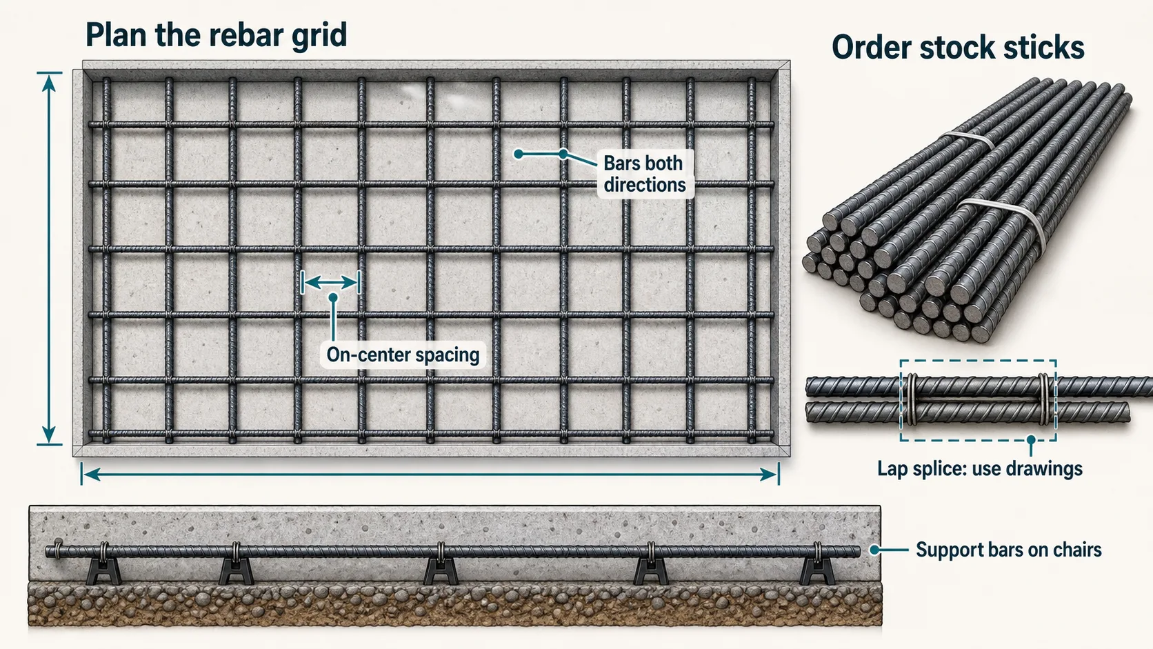
Cover comes off both ends of both dimensions, which gives the clear run each bar is cut to. The clear run divided by the spacing gives the number of gaps, and one more than that is the bar count, so the last bay is never wider than the spacing you asked for. Bar count times clear run is the steel in the mat. Then the splices: a bar longer than one stock stick needs a lap for every stick boundary it crosses, and each lap is the bar diameter times the figure on the drawing, which is why a #6 (3/4") lap is twice a #3 (3/8") lap. The calculator above counts across the full slab and applies a flat allowance instead, which is the faster way to place an order and the reason the panel under it reconciles the two.
clear = dimension − 2 × coverbars = ⌈clear ÷ spacing⌉ + 1mat = bars × clear, both wayssplices = ⌈clear ÷ stick⌉ − 1lap = bar diameter × db- Cover in use
- 3 in
- Lap in use
- 40 db, 20 in
- Allowance in use
- 10%
- Splices in your grid
- 0
This is a material takeoff, not a reinforcement design. Bar size, spacing, cover, lap class and splice stagger belong on a reinforcing drawing worked to ACI 318, and the IRC publishes no prescriptive bar schedule for a slab on ground at all.
Mesh or bar
Wire mesh, a rebar grid, or a slab that needs an engineer
Reinforcement in a slab on ground is not required by the IRC. R506.2.4 is written as where provided, which means the choice below is yours to make and yours to get wrong, right up until the slab is doing something a prescriptive answer was never meant to cover.
No reinforcement
A plain slab on a compacted base with control joints at the right spacing. The IRC does not require steel in a slab on ground, and a walk or a shed floor rarely earns it. Cracks still happen; joints decide where.
- Steel
- None
- Usual job
- Walks, shed floors
Welded wire reinforcement
Sheets rather than rolls, on chairs, lapped one full square plus 2 in. It does the same job as a light bar grid at less cost and less labour, and its whole reputation problem comes from rolled mesh being walked flat into the base.
- Steel
- 6x6 W1.4 typical
- Usual job
- 4 in patios and walks
A tied bar grid
Number 3 or number 4 bar at 12 to 18 in each way, chaired, lapped where a bar outruns a stick. This is what the calculator above counts, and it is the normal answer for anything a vehicle drives on.
- Steel
- #3 to #5
- Usual job
- Driveways, garage floors
A designed structural slab
Not a bigger grid but a different document. Bar size, spacing, cover, lap class and stagger all come off a stamped drawing worked to ACI 318, and the takeoff then follows the bar schedule instead of a spacing rule.
- Steel
- Per schedule
- Usual job
- Loads, walls, poor ground
Six slabs where a spacing rule stops being an answer
A grid at 12 in on center is a reasonable default for a slab that carries nothing but itself and a car. On any of the six below it is a guess dressed as a specification, and the honest answer is a stamped drawing rather than a heavier bar.
The slab carries a wall or a column
A line load or a point load on a slab on ground is a designed element, not a mat. Thickened sections, dowels and added bar under the load all come off a drawing.
Vehicles heavier than a car
An RV, a boat trailer, a delivery truck or a lift changes both the thickness and the steel. Wheel loads concentrate far more than a car does over the same footprint.
Expansive or poorly drained soil
Where the ground moves seasonally the slab has to span soft spots rather than rest on them, which is a stiffness problem the spacing table cannot answer.
Post-tensioning
A post-tensioned slab is not a rebar grid with cables added. It is a different design, a different layout and a different set of trades, and none of the arithmetic here applies to it.
A slab tied into a foundation
Once the slab is doweled to a stem wall or a turned-down footing, the two act together and the reinforcement has to be detailed across the joint rather than stopped at it.
Any epoxy-coated or galvanised bar
Coated bar changes both cover and lap length, and the numbers on this page assume plain uncoated bar. The coating is usually specified for a reason that also changes the detailing.
Disclaimer
These estimates are for planning purposes only. Actual costs vary by location, material availability, and project complexity. Always get at least 3 local quotes. This calculator does not replace professional advice.
Sources